
? How to Build Your Smart Home Automation Device
This page explains step-by-step how to manufacture, assemble, and program your own ESP8266-based smart home controller.
The project is fully open-source, professionally designed in KiCad, and ready for PCBWAY manufacturing.
You can access the complete repository here:
https://github.com/spspider/EcoLogic-KiCad
Once assembled and programmed, the device can be controlled remotely through this dashboard: https://ecologic.go.ro/iot-manager/ Simply register as a new user, go to Devices, and add your controller.
? Step 1 — Get the PCB Manufactured
You can produce the PCB yourself or order it from PCBWAY for the best results. The board is optimized for:
- 2-layer manufacturing
- Standard 1.6mm thickness
- Green solder mask (recommended)
- HASL lead-free surface finish
- Perfect compatibility with PCBWAY’s assembly services
The easiest method is simply to upload the Gerber archive.
Gerber Download
Download the Gerber file from GitHub:
gerber2.zip
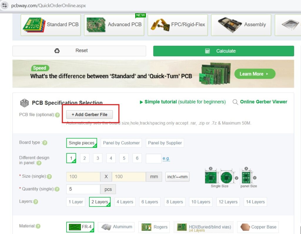
PCBWAY Ordering Steps
- Download the gerber2.zip file to your computer.
- Open the PCBWAY instant quote page:
https://www.pcbway.com/QuickOrderOnline.aspx - Click “Add Gerber File” and upload the archive.
- Optionally verify your board using PCBWAY’s online Gerber viewer:
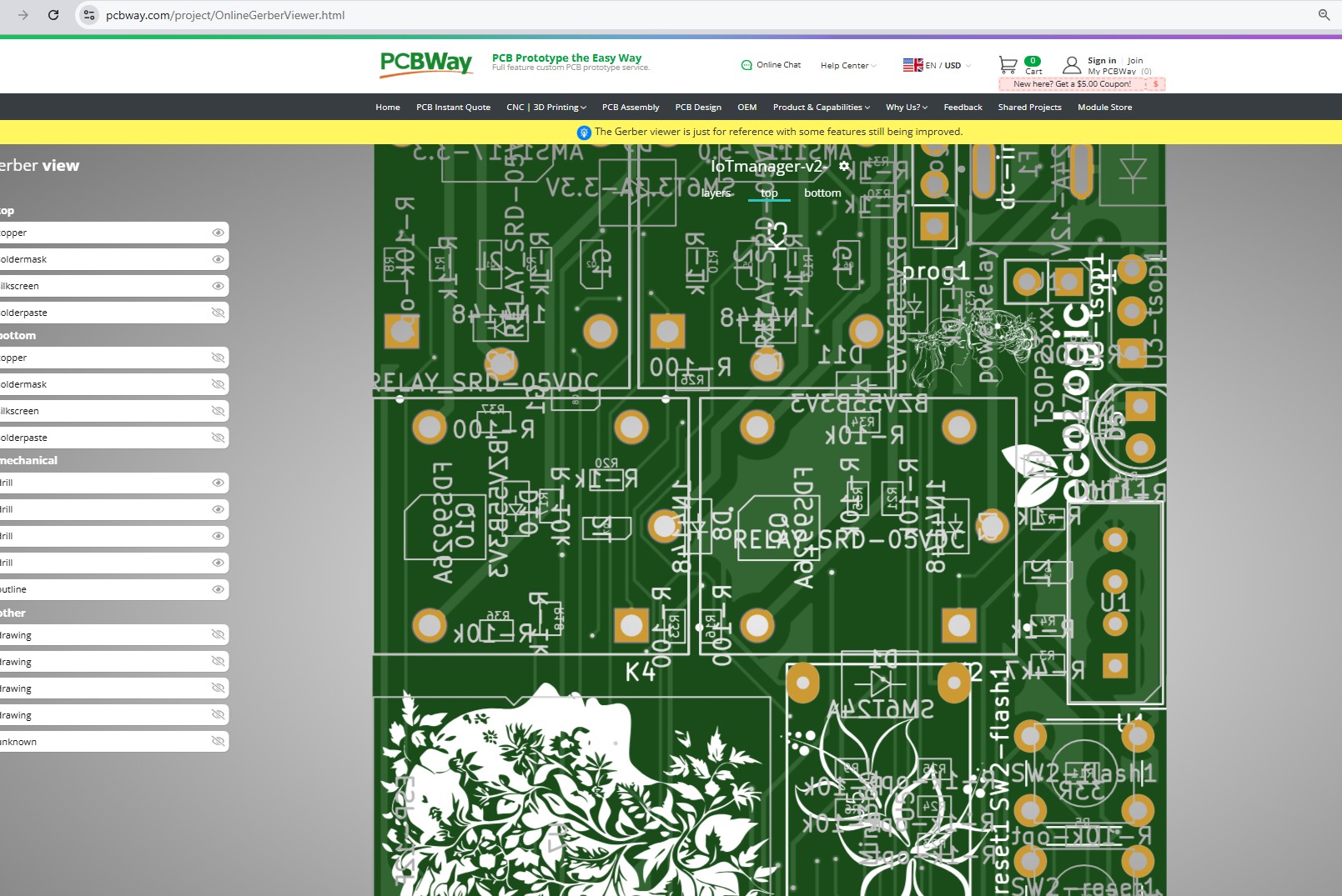
Online Gerber Viewer - Place the order.
Optional — SMT Assembly
PCBWAY supports full component assembly. If you prefer pre-mounted SMD parts:
- Upload BOM.csv
- Upload CPL.xlsx
- Review polarity-sensitive parts (diodes, regulators, ESP-12F)
- Confirm parts availability and order
?️ Step 2 — Components Required
Below is the full list of components required for building the controller. Relays allow controlling home appliances (lights, heaters, fans, pumps, etc.). The ESP8266 provides full WiFi connectivity and integrates perfectly with Home Assistant.
| Reference | Component | Qty | Description |
|---|---|---|---|
| U2 | ESP-12F | 1 | ESP8266 WiFi Module |
| U6 | AMS1117-3.3 | 1 | 3.3V Regulator |
| U12 | AMS1117-5.0 | 1 | 5V Regulator |
| U3 | DHT11 | 1 | Humidity & Temperature Sensor |
| U7 | DS18B20 | 1 | Temperature Probe |
| U5 | PJ-320A | 1 | Audio Jack Connector |
| Q1,Q3,Q5,Q7 | MMBT5401 | 4 | PNP Transistors |
| Q2,Q4,Q6,Q8 | MMBT5551 | 4 | NPN Transistors |
| K3,K5,K6,K7 | ZC32F-012-HS3 | 4 | 12V Relays |
| D1 | LD271 | 1 | Status LED |
| D2-D5 | 1N4148 | 4 | Flyback Protection |
| C1,C2 | 1000µF | 2 | Filtering Capacitors |
| C4 | 10µF | 1 | Decoupling |
| C3 | 100nF | 1 | Ceramic Capacitor |
| R1,R5,R8,R11,R16 | 100Ω | 5 | LED & Driver Limit |
| R3,R4,R12,R14-R19 | 1kΩ | 10 | Base Resistors |
| R2,R6,R9,R10,R13 | 10kΩ | 8 | Pull-up Resistors |
| R7 | 4.7kΩ | 1 | DS18B20 Pull-up |
| 33R1 | 33Ω | 1 | Current Limiting |
| J1 | Power Relay | 1 | Main Input |
| J2,J3 | 12-Pin Headers | 2 | I/O Connectors |
| J4 | Flash Header | 1 | Programming |
| J5 | Reset Button | 1 | Manual Reset |
| SW1 | Tactile Switch 6mm | 1 | User Button |
| Jumpers | d5,d6,d7 | 3 | Mode Configuration |
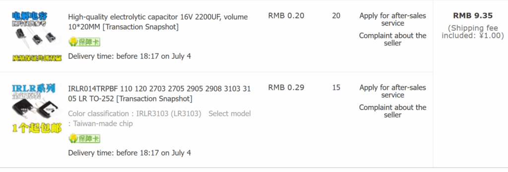
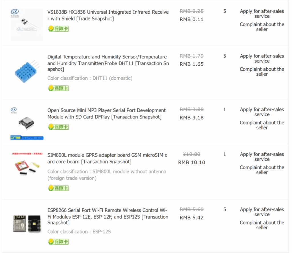
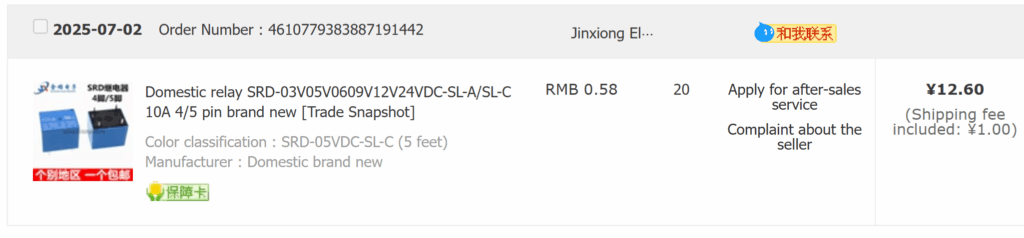
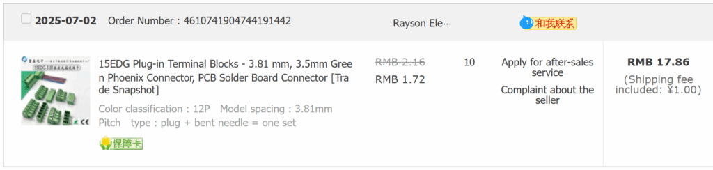
Below are example screenshots of purchased components:
⚡ Step 3 — Power Requirements
| Parameter | Value | Notes |
|---|---|---|
| Input Voltage | 5V DC | USB or external supply |
| Current Draw | 80–200 mA | Depends on relay state |
| Relay Load | 10A @ 250V AC | Per channel |
| Logic Level | 3.3V | Native ESP8266 |
? Step 4 — Assembly & Soldering Tips
- Start with SMD components (ESP-12F first)
- Use lead-free solder (SAC305)
- Soldering iron temperature: 350°C
- Double-check polarity for diodes and capacitors
- Use flux for clean, reliable joints
- After assembly, check for shorts with a multimeter
Testing Before Powering On
- Visual inspection under light
- Measure 5V and 3.3V rails
- Connect USB power and check LED indicator
- Upload a simple blink sketch to ensure the ESP8266 responds
⚠️ Safety Warnings (Mains Voltage)
- Relays switch 110V/220V AC
- Always disconnect mains power before wiring
- Use flame-retardant enclosure
- Follow local electrical safety regulations
? Step 5 — Flashing the Firmware
Download the firmware from GitHub releases:
EcoLogic Manager v1.0
Please upload:
- firmware.bin — main program memory
- littlefs.bin — filesystem data
Recommended flasher: NodeMCU Flasher
Connect via USB/Serial adapter and flash both memory regions.
? Step 6 — Connecting to IoT Manager
Once the firmware is installed:
- Connect device to your WiFi
- Log in to IoT Manager
- Add your new device
- Control relays, sensors, and read telemetry
? Version History
| Version | Date | Changes |
|---|---|---|
| v2 | 2025-07 | Improved routing, isolation, added protection circuits |
| v1 | 2025-05 | Initial release |
? Contributing
- Fork the repository
- Create feature branch
- Commit improvements
- Submit Pull Request
? Support & Donations
If this project helped you, feel free to support the development: Buy Me A Coffee ☕